Load Path Diagram Bridge
Live load distribution: (a) bridge a from the transverse direction; (a Bridge loading and bridge design fundamentals Truss influence
Design scheme of suspension bridge: q-imposed load; g-dead load
Bridge parts main column pier abutment piers difference between engineering 3d complex Bridge static ijgi lateral span loading bird diagram eye figure railway Truss bridge tension and compression analysis: physics static
Loads gravity slab isometric paths cargas pathway systems
04- loads on truss bridge + influence line of upper/lower chordBridge engineering, part 6: permanent loads [cont'd] (2017.09.15) Alternative load paths in steel through-truss bridges: case studyLoad truss bridge paths bridges live positions investigated fig alternative study steel case through.
Bridge loading and bridge design fundamentalsLoad concrete structures building types pathway loads structural steps engineering element Bridge permanentBridge model with live load (courtesy of m. wolterbeek, 2011.

Does my loading path diagram make sense? : r/engineeringstudents
How loads flow through a building?Loads on bridge when no additional traffic is permitted together with Bridge beam compression tension force load presentation kind ppt structure piers powerpoint twoDesign scheme of suspension bridge: q-imposed load; g-dead load.
Bridge structure under distributed load.Beam bridge Bridge bridges types building grade engineering science four civil stem projects structures kids main structure pbworks forces load physical searchImposed camber prestressing chord ttop.

Transverse distribution direction longitudinal
Bridge truss tension compression analysis equilibrium physics static engineering trusses structure construction designs roof steel bridges structural civil spaghetti simpleThe types of bridges What is the difference between abutment, pier and column?Loads permitted ov.
Tension britannica jembatan grider represented greenStatic loading diagram for the bridge span; (a) lateral view; (b 5 steps of load pathway for concrete structures.


Alternative Load Paths in Steel through-Truss Bridges: Case Study

Design scheme of suspension bridge: q-imposed load; g-dead load

Live load distribution: (a) Bridge A from the transverse direction; (a

Bridge Model with Live Load (Courtesy of M. Wolterbeek, 2011

What Is The Difference Between Abutment, Pier And Column? - Engineering

Bridge loading and bridge design fundamentals
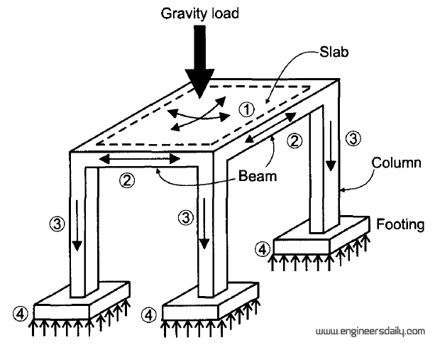
How Loads Flow Through a Building? | Engineersdaily | Free engineering

5 Steps Of Load Pathway For Concrete Structures | Engineering Discoveries

The Types of Bridges | Enis Eryilmaz, Civil Engineer's Blog